Features
- Can use existing or new transmitters or transceivers
- Runs under Windows® operating system
- Each encoder can service two transmitters
- Can support MF, HF and VHF radios simultaneously
- Up to 20 transmitters on a single PC
- No limit to the number of encoders on a network
- An encoder can receive DSC messages from one or more operator consoles
- Can queue messages for transmit if radio is busy
- For A3 stations the encoder can limit the available DSC frequencies by radio
About
The TransOceana DSC Encoder is a Windows® software application that runs on an industrial rack mount computer, a desktop computer or a laptop. The encoder is used to convert the DSC messages from an operator console into audio signals which are then sent to a transmitter. The encoder can key the transmitter, change frequencies and verify the state of the transmitter before transmitting. It uses an internal or external audio interface module (soundcard) to send audio signals to a transmitter. Each encoder can service two transmitters, Transmitter 1 and Transmitter 2. Transmitter 1 can be a MF or HF or VHF radio and Transmitter 2 can be a MF or HF or VHF radio. The radios do not have to be the same. One encoder can service both transmitters simultaneously. Both radios can transmit at the same time.
Multiple encoders can be placed on a single PC to handle more transmitters. The number of encoders on a single PC is limited to the memory and cpu speed of the PC. Each encoder can receive DSC messages from one or more operator consoles on the network. An internal queueing system is used to hold messages while the transmitter is busy.
A transmitter can be ‘shared’ by multiple consoles with different MMSI numbers. For example, Coast Guard could share its DSC VHF radios with the local shipping port or Navy. When a DSC message is transmitted it uses the specified MMSI # of the console.
An encoder can key a transmitter in several ways:
1. By sending a control command over a serial link to the radio.
2. VOX signalling where the transmitter keys when the audio signal is above a specified threshold.
3. Using a small signal relay to open/close a PTT control line to the transmitter
Each transmitter has its own configuration file for specifying how the transmitter should be setup prior to a DSC transmit. This can include setting transmitter parameters such as power level, mode, external amplifiers, etc. and additionally setting the frequency if required. The encoder can also verify each of these settings to make sure the transmitter is ready before keying the PTT line. Each transmitter can be configured to limit the number of available DSC transmit channels. This is useful if a particular transmitter is not able to transmit on some frequencies due to antenna or amplifier restrictions.
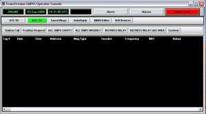
Operator console
An operator can transmit a DSC message with as few as 3 key clicks. Pre-defined messages are used to simplify the task. A log of all messages transmitted is stored on disk for later reporting. The status of all transmit jobs is displayed on the console. If a DSC message cannot be transmitted for some reason then an alarm is sounded to notify the operator.
Custom DSC messages can be sent. This includes every possible message permitted in the DSC protocol exceeding the requirements for a Class A station.
For A3 transmitters the operator is given a drop down list of available DSC channels to select from. This restricts the operator to only those valid channels that are available for that transmitter. This is not needed for VHF and MF transmitters which are single channel transmitters.
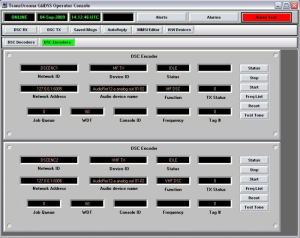
DSC encoder handler
The status of each encoder is displayed on the operator console using a DSC Encoder panel. Multiple encoders are stacked on top of each other in a manner similar to a 19″ equipment rack. The user can scroll up and down the stack to view the status of each encoder. The operator can temporarily suspend the operation of each encoder and restart it as required. The communications link between each encoder and operator console is monitored using a software watchdog timer. If the communications link fails an alarm is sounded to alert the operator.