Maritime Software

TransOceana and its associates are industry professionals with 20+ years experience in government and private sector marine safety & communications.
To view information about the company.
We’re a global leader in the design and implementation of PC-based DSC, NBDP, NAVTEX and radio control software components for use in GMDSS A1, A2, A3 shore stations, control centres and monitoring stations. We make state of the art maritime technology available at costs within the budget of even small countries.
Features
- The most advanced shore station system available today
- Display DSC traffic from up to 100 receivers
- Transmit DSC messages to 100 various transmitters
- Advanced auto reply features to DSC messages
- Integrated advanced NBDP functions
- Integrated advanced NAVTEX functions
- Relay controls for remote sites
- RadioTelephone control panels
- User configurable for 'simple' or 'advanced' displays
- Multiple consoles on a single PC
- No limit to the number of consoles on a network
- Virtual Receivers for filtering DSC traffic
- Custom alarms and alerts
- Custom log files and reporting
- Custom MMSI database for displaying vessel names
- NMEA and AIS interfaces to other systems
- Advanced DSC message error correction algorithms
- Advanced DSC message displays
- Synthetic receivers function for combining DSC messages to remove errors
- Linking consoles across borders to facilitate quick response to distress and safety calls
- DSC message Database for archiving, searching and reporting function
About
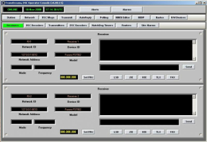
The TransOceana GMDSS Operator Console is the most advanced GMDSS shore station console in the world, providing features and networking capabilities that exceed other existing shore station systems available today. The Console is a software application that runs on the Windows® Operating System. The Operator Console is used to receive and transmit DSC messages, send and receive NBDP traffic, send and receive NAVTEX traffic, provide radio control over various radiotelephone equipment, and monitor various hardware assets. The Console software can run on an Industrial Rack Mount PC, a desktop PC or a laptop. Multiple operator consoles can run on the same PC if required. For more information regarding GMDSS technology and systems see the Dunstan and Associates' web site (http://www.gmdss.com.au). Glenn Dunstan is an internationally recognized expert in GMDSS regulatory issues and TransOceana has installed many systems in cooperation with his group.
Receiving DSC Message
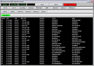
An Operator Console can be user configured to display received DSC messages. This is done by adding one or more ‘Virtual Receivers’ which are software ‘pages’ that filter the traffic as required and display them on a separate page. Each virtual receiver can be accessed by clicking a button assigned to the receiver. Each virtual receiver can filter DSC traffic based on more than 30 different filters in any combination. Detailed information about each message can be displayed by clicking on the message.
Each filtered message can be logged in various types of report files for later processing. Each message can also trigger a user specified alarm to notify the operator that a message has been received. Position messages can be reformatted into NMEA or AIS sentences and sent to other software applications on the network. Each virtual receiver can also auto reply to Test Calls and any other type of message as required.
Using ‘synthetic receiver analysis’ a virtual receiver can combine the received DSC messages from various receiver sites and process them to remove bit errors. For example, if a country has 2 MF receiver sites, the messages from both sites can be combined to remove bit errors from each site to produce clean messages. A virtual receiver can also be used to search through the DSC message database and display messages meeting a specified criteria. For example, all traffic over the last 30 days for vessel xxxx can be displayed.
Transmitting DSC Message
The Transmit function is used to send DSC messages. Using pre-defined buttons the operator can quickly send the most common messages with only two key strokes. Custom messages display a screen where the operator can create literally any kind of DSC message permitted under the DSC specification. This exceeds the requirements for Class A DSC equipment. The transmit log shows all messages transmitted and the current status of any pending transmissions. Alarms are used to alert the operator if a transmission fails. Multiple consoles can share one or more transmitters. Alternatively, specific transmitters can be limited to specific consoles.
User-define DSC message
The operator can pre-define custom messages that are frequently sent and save them in the ‘Saved Messages’ function. There is no limit to the number of custom pre-defined messages. With one click the operator can send any custom pre-defined message. The operator can also configure any custom pre-defined message to automatically transmit at given intervals or on a specified schedule. For example, if polling a fishing fleet for position reports, a custom message can be created which sends a position request message as a group MMSI call and to send the request once each four hours. Custom pre-defined messages are useful for quickly testing receivers and transmitters between shore stations to verify the system is working correctly. Each console can define its own custom messages. This is useful for site Consoles, regional Consoles and technician Consoles where each would have different types of messages.
MMSI Database
Each Console has its own MMSI database which is used to display a vessel name instead of the MMSI on a DSC message. If the MMSI is not found in the database the MMSI is displayed instead. The operator can easily add new entries to the database, change entries or remove entries. The database can be shared among Consoles and exported/imported to other stations.
NBDP Function
The NBDP function can send and receive FEC and ARQ NBDP traffic. Each NBDP modem is displayed in a user panel. Up to 100 modems can be added to each Operator Console. The panels are stacked vertically as if in a an equipment rack.
NAVTEX Function
The NAVTEX function can send and receive NAVTEX broadcasts. Each NAVTEX station is displayed in a panel and each Operator Console can support up to 100 NAVTEX stations. The NAVTEX transmit panel, is used to create and edit messages. The automatic broadcast schedule is configured into the NAVTEX handler. Multiple Consoles can interface to a single NAVTEX station.
Hardware Device Monitoring
The H/W devices function is used by the Console operator to monitor and control the various hardware elements that make up the station. These include Radios, Decoders, Encoders, Relays, etc. Each device type can display up to 100 device panels arranged in a stacked format similar to a 19″ rack mount. Each device is continuously monitored using a software watch dog timer and any problems result in visual and audible alarms. All alarms are recorded in an event log. Multiple Consoles can monitor the same devices, or specific Consoles can be configured to monitor specific devices. For example, local Consoles may monitor radios and relays while a central command station may monitor only the radios.
FEATURES
- Can use existing or new NAVTEX transmitters
- Integrated into the GMDSS Operator Console
- Up to 100 NAVTEX transmitters can be supported
- A single NAVTEX station can be accessed from multiple Consoles
- Broadcasts can be scheduled and/or sent manually
- Distress button to quickly send NAVTEX distress messages
- User-defined message templates
- Start of message and end of message can be custom designed
- Automatic date insertion into messages
- Virtual NAVTEX stations can share a common transmitter
- One minute audible alert of scheduled broadcast start
ABOUT
The TransOceana NAVTEX function can be used to both send and receive NAVTEX broadcasts. The NAVTEX function is a software based Windows application integrated into the GMDSS Operator Console. Any number of NAVTEX monitoring receivers and broadcast transmitters can be supported. NAVTEX broadcasts can be both manual and scheduled. Distress broadcasts can also be made. Multiple Operator Consoles can share the same NAVTEX transmitter or receivers.
NAVTEX TX HANDLER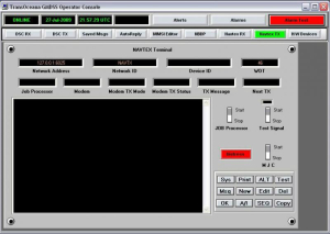
The NAVTEX TX handler is a Windows® based software application that runs on an industrial PC, desktop PC or laptop. The handler interfaces the Operator Consoles to the NAVTEX transmitters. Each handler can support up to 100 transmitters. The handler includes a ‘Job Scheduler” that will automatically transmit a NAVTEX broadcast on a scheduled basis. The scheduler includes the message database such that it can independently broadcast even if the network to the Operator Consoles is inoperative. The handler monitors the status of the transmitter and reports any faults to the Operator Console.
NAVTEX RX HANDLER
The NAVTEX RX handler is a windows based software application that runs on an industrial PC, desktop PC or laptop. The handler interfaces the operator consoles to the NAVTEX receivers. Each handler can support up to 100 receivers. The RX handler functions independent of the TX handler. It is used to receive NAVTEX broadcasts and pass them to the operator consoles. This is normally used for monitoring the stations broadcasts but can be used to monitor other stations as well. The RX handler can be installed on different PC’s than the TX handler or on the same PC. The number of receivers can be different from the number of transmitters. The RX handler can be used solely as a monitoring device with no transmit function at the station. The RX handler is compatible with most NAVTEX receivers on the market today.
NAVTEX OPERATOR CONSOLE
Each Operator Console can be configured to interface to one or more NAVTEX transmitters. Multiple transmitters will appear as separate panels as shown above stacked vertically as if in a 19″ rack. The NAVTEX panel is used to interact with the NAVTEX TX handler (described above). The Operator can create messages, edit messages and remove messages from the broadcast schedule. The job processor running on a TX handler can be stopped and started as needed. Stopping the job processor will sound an audible and visual alarm on all Consoles connected to the transmitter to alert the station operators of a change in status. One minute before each scheduled broadcast an audible and visual alert is sounded on the consoles to notify the operators of a broadcast start.
A ‘test signal’ can be activated at any time by the operator for maintenance purposes. A distress button can be used to immediately send a NAVTEX distress message.
A distress message will pre-empt any transmission currently in progress. A “MJC” (manual job control) function is available whereby the operator can manually send messages thereby overriding the scheduled broadcasts. By turning off the Job Scheduler and using the MJC feature the NAVTEX station can be operated manually. This is useful during testing and station setup. A test feature can be used to simulate a scheduled broadcast to insure the correct messages are being sent, and are in the correct order. Additionally the test function can be used to verify that the transmission will fit within the allotted time frame available for transmission.
The NAVTEX function is capable of transmitting all NAVTEX message types. The operator can create custom message templates and save them on the TX handler. These templates can be called into the editor where current information can be entered into the message and then added to the broadcast schedule. This eliminates having to enter the same text each time. The operator can create Job Start text and Job End text which is placed at the start and end of each transmission. This can include station information, location, frequencies for contacting the station, etc. In addition, in the Job Start template the operator can specify the insertion of the current date and time into the message.
DSC Decoder I
Features
- Can use existing or new radio receivers or transceivers
- Runs under Windows® operating system
- State of the art DSP signal processors
- Captures more DSC signals than any other decoder on the market
- Each decoder can service 2 radios
- Can support MF, HF and VHF radios simultaneously
- Up to 20 radios on a single PC
- No limit to the number of decoders on a network
- Parallel signal processors on each radio can capture message collisions
- A decoder can send messages to one or more operator consoles
- Internal memory to store up to 65,000 messages in case of network failures
- Passes all information down to the bit level on each message for subsequent processing
- Can decode the new expanded DSC sentences for enhanced position information
About
The TransOceana DSC decoder is a Windows® software application that runs on an industrial rack mount computer, a desktop computer or a laptop. The decoder is used to convert the DSC audio signals from a radio receiver into a digital DSC message and send the message to a GMDSS operator console on the same PC or over a local area network to one or more operator consoles. It uses an internal or external audio interface module (soundcard) to receive the radio audio signals. Each decoder can service two radios, radio 1 and radio 2. Radio 1 can be a MF or HF or VHF radio and Radio 2 can be a MF or HF or VHF radio. The radios do not have to be the same. Multiple decoders can be placed on a single PC to handle more radios. For example, an A3 station would run 3 decoders on the same PC:
Decoder 1: 2Mhz, 4Mhz
Decoder 2: 6Mhz, 8MHz
Decoder 3: 12Mhz, 16MHz
The number of decoders on a single PC is limited to the memory and CPU speed. We have tested systems successfully with as many as 14 DSC receivers on a single PC. Each decoder can be configured to send the DSC messages to one or more operator consoles on the network. The decoder is limited to a maximum of 100 operator console addresses.
Operator console
The DSC messages from the decoders are displayed on one or more operator consoles. The display can be filtered to show messages from selected decoders or from all decoders. If the network between the decoder and the operator console should fail, the decoder will continue to capture traffic and store it locally. When communications is restored the decoder will automatically update the console with all lost messages.
DSC decoder handler
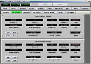
The status of each decoder is displayed on the operator console using a DSC Decoder panel. Multiple decoders are stacked on top of each other in a manner similar to a 19″ equipment rack. The user can scroll up and down the stack to view the status of each decoder. The operator can temporarily suspend the operation of each decoder and restart it as required. The communication link between each decoder and operator console is monitored using a software watchdog timer. If the communication link fails an alarm is sounded to alert the operator.
DSC Decoder II
Features
- Black Box decoder
- Operator Console connection not required
- DSC messages are output using serial or UDP methods
- Can filter messages
- Can output to multiple destinations
- Can operate stand-alone as a DSC message recorder
- Ideal for decoding DSC traffic and passing to 3rd party software
About
The DSC Decoder II is a Windows® based software component for decoding DSC signals and passing the messages to 3rd party software using serial or UDP/IP connections. The standard DSC decoder requires connection to an operator console to view the messages. The DSC Decoder II does not require connection to an operator console. The DSC Decoder II is ideal for applications that require only DSC signal capture and reporting, e.g. receiving DSC message reports and passing the information to an AIS chart plotting system.
The DSC Decoder II is an integration of the standard TransOceana DSC decoder and the TransOceana GMDSS operator console. In the past if a 3rd party application wanted to capture DSC messages and report them on a web page or a chart they would need to purchase both a DSC decoder and GMDSS operator console software components. The DSC decoder would decode the signals and send them to the operator console. The operator console would use a virtual receiver to reformat the messages and send them to a 3rd party application using either AIS or NMEA protocols.
With the DSC Decoder II the decoder can send the DSC messages directly to the 3rd party application. There is no need for an operator console. However a DSC Decoder II can be configured to output DSC messages to BOTH 3rd party applications and one or more operator consoles if required.
The decoder can be configured to filter messages similar to a virtual receiver in the GMDSS operator console program. An operator console can have 10 virtual receivers and therefore 10 different filtering methods, the DSC Decoder II is limited to one filter per radio. If more than one filter is required then the decoder must pass its messages to a virtual receiver (operator console). The DSC Decoder II provides a less expensive solution for those applications requiring only DSC messages.
A DSC Decoder II can also be used as a stand alone DSC message recorder. The decoder can be configured to capture messages and store them into a report file to be accessed later by the user. For example, the decoder could be used to log all station calls to a specific MMSI.
Features
- Can use existing or new transmitters or transceivers
- Runs under Windows® operating system
- Each encoder can service two transmitters
- Can support MF, HF and VHF radios simultaneously
- Up to 20 transmitters on a single PC
- No limit to the number of encoders on a network
- An encoder can receive DSC messages from one or more operator consoles
- Can queue messages for transmit if radio is busy
- For A3 stations the encoder can limit the available DSC frequencies by radio
About
The TransOceana DSC Encoder is a Windows® software application that runs on an industrial rack mount computer, a desktop computer or a laptop. The encoder is used to convert the DSC messages from an operator console into audio signals which are then sent to a transmitter. The encoder can key the transmitter, change frequencies and verify the state of the transmitter before transmitting. It uses an internal or external audio interface module (soundcard) to send audio signals to a transmitter. Each encoder can service two transmitters, Transmitter 1 and Transmitter 2. Transmitter 1 can be a MF or HF or VHF radio and Transmitter 2 can be a MF or HF or VHF radio. The radios do not have to be the same. One encoder can service both transmitters simultaneously. Both radios can transmit at the same time.
Multiple encoders can be placed on a single PC to handle more transmitters. The number of encoders on a single PC is limited to the memory and cpu speed of the PC. Each encoder can receive DSC messages from one or more operator consoles on the network. An internal queueing system is used to hold messages while the transmitter is busy.
A transmitter can be ‘shared’ by multiple consoles with different MMSI numbers. For example, Coast Guard could share its DSC VHF radios with the local shipping port or Navy. When a DSC message is transmitted it uses the specified MMSI # of the console.
An encoder can key a transmitter in several ways:
1. By sending a control command over a serial link to the radio.
2. VOX signalling where the transmitter keys when the audio signal is above a specified threshold.
3. Using a small signal relay to open/close a PTT control line to the transmitter
Each transmitter has its own configuration file for specifying how the transmitter should be setup prior to a DSC transmit. This can include setting transmitter parameters such as power level, mode, external amplifiers, etc. and additionally setting the frequency if required. The encoder can also verify each of these settings to make sure the transmitter is ready before keying the PTT line. Each transmitter can be configured to limit the number of available DSC transmit channels. This is useful if a particular transmitter is not able to transmit on some frequencies due to antenna or amplifier restrictions.
Operator console
An operator can transmit a DSC message with as few as 3 key clicks. Pre-defined messages are used to simplify the task. A log of all messages transmitted is stored on disk for later reporting. The status of all transmit jobs is displayed on the console. If a DSC message cannot be transmitted for some reason then an alarm is sounded to notify the operator.
Custom DSC messages can be sent. This includes every possible message permitted in the DSC protocol exceeding the requirements for a Class A station.
For A3 transmitters the operator is given a drop down list of available DSC channels to select from. This restricts the operator to only those valid channels that are available for that transmitter. This is not needed for VHF and MF transmitters which are single channel transmitters.
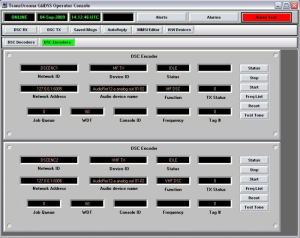
DSC encoder handler
The status of each encoder is displayed on the operator console using a DSC Encoder panel. Multiple encoders are stacked on top of each other in a manner similar to a 19″ equipment rack. The user can scroll up and down the stack to view the status of each encoder. The operator can temporarily suspend the operation of each encoder and restart it as required. The communications link between each encoder and operator console is monitored using a software watchdog timer. If the communications link fails an alarm is sounded to alert the operator.
Features
- A USB hardware relay module
- 4 relays per module
- Max 100 modules per operator console
- NC/NO configuration for each relay
- Small signal or large signal relays available
- Any relay can be accessed from one or more consoles
- Relay status is updated instantly on console
About
The TransOceana Relay Control feature integrates small signal hardware relay control into its GMDSS Operator Console software program. The relays can be used to toggle PTT on radio transmitters, activate lights, alarms, door locks, etc. Each relay module provides 4 relay contacts. Up to 100 relay modules can be added per operator console.
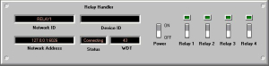
The relay handler panel is displayed on the operator console under H/W devices. There is one panel for each hardware module. Each module provides 4 small signal or 4 large signal relays. Each relay can be configured for NO or NC operation. The relay status is updated frequently and displayed as an indicator lamp above each switch. The entire module (all 4 relays) can be powered off with a single switch.
For larger systems, each console can be configured to display selected relay modules. For example, an administrative console can be configured to not display any relays handlers. A technician console can be configured to display only those relays within a certain geographic region.
About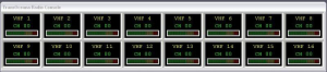
The new TransOceana Radio Control function is a Windows® based software application and hardware audio switching matrix that provides a flexible yet convenient system for controlling multiple radio-telephones. Up to 100 radios can be configured into a user defined matrix control panel for viewing status and changing channels. Multiple consoles can share the same radios.
Radio Control Handler
The Radio Control Handler is a Windows® based software application that can run on an industrial PC, desktop PC or laptop. The handler interfaces the operator console Radio Control function to one or more external audio matrix modules for routing audio signals to and from multiple radios. The radio handler can support multiple operator consoles which can all share the same radios. The handler controls all audio routing from one or more microphones or headsets to the radios. The handler also controls all audio routing from the radios to one or more speakers or headsets. PTT keying and channel changing are controlled by the handler through various radio handlers. The handlers can also monitor the status of the radios and update the operator consoles.
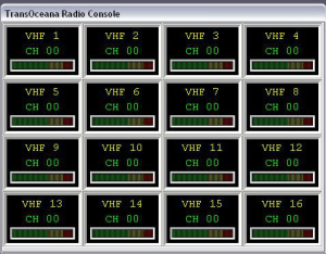
Operator Console Radio Control Panel
- Multiple radios can be quickly accessed from a single panel that can be placed anywhere on the PC desktop.
- The panel can be displayed in any row and column configuration.
 The radios can be of different types including MF, HF, VHF and can be receivers only, transmitters or transceivers. They can be mixed of any type and number. The radios can be ordered any place in the matrix.
- Each radio can have its own descriptive name. Each radio indicator will display the radio name, channel and signal strength.
- If the radio is ‘selected’ then its background will appear yellow.
- If the radio is transmitting its background will appear red.
- Clicking on a radio is used to select the radio and to change the channel.
The radio channel can be entered directly using the keypad, or a pre-defined channel can be selected by pressing one of the macro keys. The user can create custom macro keys by entering a text name for the key and the channel it is assigned to.
A channel translate table for each radio is used to translate user channels or text into radio channels. For example, a button could be configured as “WRK 1″ and assigned to CH 26. Each radio is
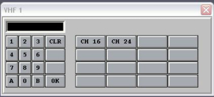
configured with the valid radio channels for that radio. The operator cannot change the channel to any other channel not assigned. This feature works even if the radio does not support channel lockout. Each radio is also accessible from the H/W devices panel in the operator console:
- Each radio panel in the H/W devices list can be assigned to the Radio Control panel matrix. The user can specify which radios in the list will be added to the Radio Control matrix.
- The radio panel in the H/W devices will indicate the same information as the Radio Control panel but provides more information about the radio including fault conditions if available from the radio.
- Each operator console can be configured independently to which radios are monitored and displayed. Multiple microphones are supported as well as multiple speakers.
- The operator can route the audio from one radio to multiple speakers or a single speaker. The same with microphones.
Features
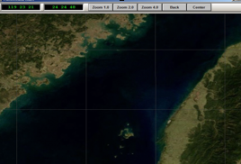
- Mapping program indicates relative position of vessels reporting in a DSC transmission
- Mapping screen can be centered on distress or at operator’s discretion
- Mapping screen can display chart or map available to operator in a .jpg format
- One click access to map from regular console display or can be displayed on split screen if operating system allows
- If there is a distress call, the position of the vessel in distress flashes to alert operator to vessels in the area that could respond
- Mapping is integrated into the operator console and is an option available with purchase of console
- No separate interface needed to install mapping
About
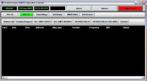
The TransOceana map function option runs on the TransOceana Operator Console application. The map function provides an easy to use method for displaying ship locations on a regional map without having to purchase or interface to 3rd party map applications.
If a DSC message is received with a position, then the map is automatically updated with the location and MMSI of the vessel. This feature is integrated with the virtual receivers within the operator console to selectively filter what is added to the map. The map display always centers on the last position added making it easy to locate the vessel.
Landmarks and positions of other special interest can be added to the map and saved in a database. Layers can be defined by the operator to add or remove location types. By integrating the map function with a virtual receiver, an alert can be sounded when the map is updated. For example, if a distress call within a geographic area is received, the map will be updated and an alert sounded.